Although the CNC inlay process is a moderately simple, the v-carved inlay can be a little tricky to understand at first. With this explanation and a few tries out in the shop, the mystery will disappear. Let’s start at the beginning.
Anatomy of the V-Carved Inlay
A V-Carved inlay is a pairing of a pocket cut (negative) and a mating inlay (positive). Each toolpath has 2 critical settings: the Start Depth and the Flat depth. The values for each of these depths will determine the final thickness of the inlay, the glue gap left at the bottom of the inlay, and the saw blade gap left for cleanup.
In most cases, the saw blade gap is of little consequence but is discussed here because the final depth of the inlay will change that gap and you need to understand how.
I use a software called Desktop-Pro from Vectric to generate my tool paths and generate my g-code. This software is 1/2 CAD and 1/2 CAM so I can do a lot of things with it. I am not familiar with other CAM software but I have little doubt that all can define inlays and will have similar terminology.
I will get right to the point of this article. For definitions and other nice things to know, read through the entire article.
Choosing Start Depth and Flat Depth
Many online resources describe how to set the Start Depth and Flat Depth for V-Carved inlays but thay all seemed to miss some information. Hopefully, this article will fill in the information that I found lacking in the rest.
The 4 depths in a VCarve toolpath
There are 4 depths you can manipulate when setting up your toolpath – they are:
- Pocket Start Depth
- Pocket Flat Depth
- Inlay Start Depth
- Inlay Flat Depth
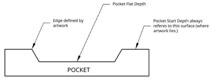
First, the Pocket Start Depth is always set to zero or the top of the pocket work piece. This point will always coincide with the start depth of the insert piece. The Pocket Start Depth always sits on the plane that the artwork has been defined on. So, just remove the Pocket Start Depth from your list of variables that you have to manuipulate.
That leaves 3 variables that can be altered to achieve the result your inlay requires. Staying with the pocket piece, the remaining variable to be set is the Flat Depth.
The 3 depths that are left in a VCarve toolpath…
Pocket Flat Depth
The pocket Flat Depth will define the bottom of the glue gap. It must be larger than the Inlay Start Depth and the difference in the 2 depths will be the glue gap.
With that, the pocket workpiece is defined (I told you it wouldn’t be complicated.)
Inlay Start Depth
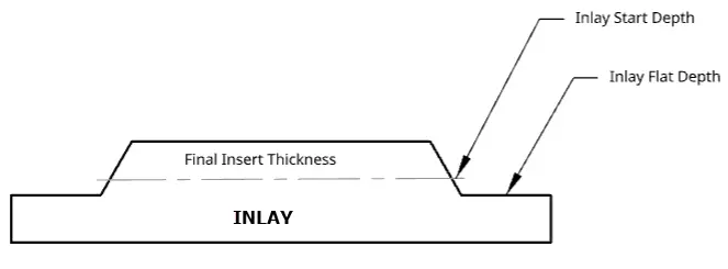
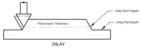
The Inlay Start Depth will determine where the point of the v-bit will consider Z Zero for the tool path. The bit will then plunge a depth determined by the g-gode and continue to step down until it reaches the Inlay Flat Depth. This depth is adjusted in the g-code to follow the angle of the bit (see Figure 3).
Inlay Flat Depth
The last variable is not as critical but has to be larger than or equal to the Inlay Start Depth. The difference between the Inlay Start Depth and the Inlay Flat Depth will create – what I am calling – the saw gap (See Figure 4). This is the gap in the inlay that a bandsaw blade might run through during final cleanup. It is not critical because the bandsaw blade will cut through the waste if the gap is there or not but a lot of the other articles mentions that the Inlay Flat Depth has to be a certain depth and I just do not find that to be true – as long as it is larger than or equal to the Inlay Start Depth.
The saw gap will also allow for glue squeeze out. If there is no saw gap, there might not be enough area for the glue to squeeze out during glueup. Since liquids do not compress, this might (most likely will) cause gaps between the inlay and the pocket that will not look nice.
Last Thoughts
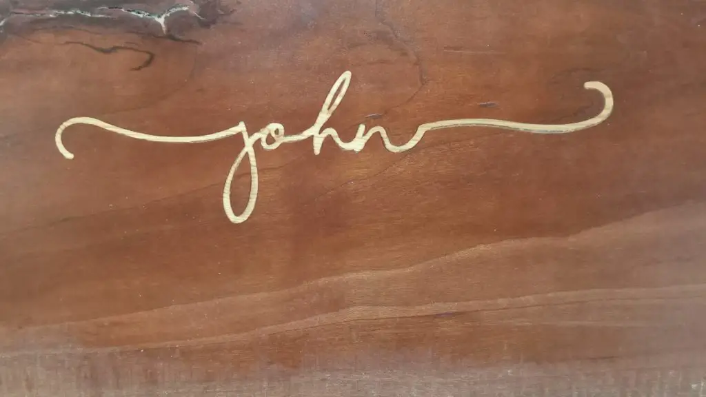
The Artwork
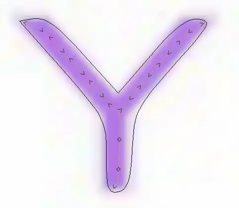
The inlay process all starts with the artwork. This is the image tat you will be duplicating in the wood. the best artwork will come in a vector format made up of straight lines and curves. While bitmap images can be used, they must be converted to vector files as well. Converting bitmaps to vector files can result in uneven lines as the “tracing” software tries to trace around each pixel.
Combined with the reality that most bitmap images try to blend edges into the background will prevent the tracing software from detecting exactly where the edges occur. this, in turn, can lead to extra tool movements and lines tat are not straight.
In the image below, you can see where a block letter has turned into a letter with very rounded edges and corners. This does not make it impossible to use bitmap files but it does make it more difficult to fit an inlay into a pocket. This was also an image that had to be enlarged before applying the bit trace. Black and White images and images that do not have to be enlarged often work well for CNC Inlays.
Types of Vector Files
| SVG | Scalable Vector Graphics |
| Portable Document Format | |
| EPS | Encapsulated Post Script |
| CDR | Coral Draw |
| AI | Adobe Illustrator |
| Software Specific | Some CAM software have their own file extensions such as .CRV fro VCarve Pro files. |
Geometry Definitions
Glue Gap
The glue gap is a critical calculation. For larger inlays, a large glue gap may produce a hollow sound when you tap on it. This often creates a lack of confidence in the work but really does not affect the work otherwise unless the thickness of the inlay is compromised.
Since liquids do not compress and there might not be an escape route for the glue, some amount of glue gap is typically calculated in the design.
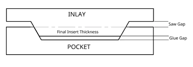
As you can see, the glue gap is the difference between the Pocket Flat Depth and the inlay Start Depth. Adjusting either Pocket Flat Depth or the inlay Start Depth will affect the glue gap and the Pockey Flat Depth must always be greater than the Inlay Start Depth.
Saw Gap
Refer to Figure 3. Saw Gap is something I am calling the gap between the finished surface of the pocket piece and the waste material on the inlay piece. I had to call it something to identify it for this article. The purpose of the saw gap is questionable but since many forums I have read had comments from people who used a band saw to cut off the excess inlay material, I included the term. There may be times when no saw gap is prefered and I will explain how to achieve that if needed. Be mindful that no saw gap will also block any glue squeezeout and that may cause gaps in the sides of the inlay and pocket.
Inlay Thickness
Refer to Figure 3. The inlay thickness is the final thickness of the inlay after the wast has been removed. The further into the pocket the inlay can go (decreasing the glue gap) the more solid the inlay will sound.
Start Depth and Flat Depth
Start Depth (Refer to Figure 2.)
Start depth is the plane where the point of the v-bit will start. On the pocket piece, the start depth is the top surface of the piece. Usually, this will be Z-zero.
Vetric.com defines Start Depth as “Start Depth (D) specifies the depth at which the V-Carving toolpath is calculated, allowing V-Carving / Engraving to be machined inside a pocket region.”
Flat Depth (Refer to Figure 2.)
Flat depth is used to create a flat bottom rather than letting the v-bit cut all of the way to a point. Vetric.com describes Flat Depth as an option that “limits the depth that the tool(s) will machine to, and is used for Flat Bottomed Carving and Engraving.” With the VCarve Pro software (that I use), VCarving can have a clearing bit defined also. A Clearing Bit – usually an square end mill – can have a larger step-over and can reduce the time it takes the v-bit to clear out the flat area. Software like VCarve Pro will calculate the correct tool path for the clearance bit so it will not cut away any of the surface cut by the v-bit.
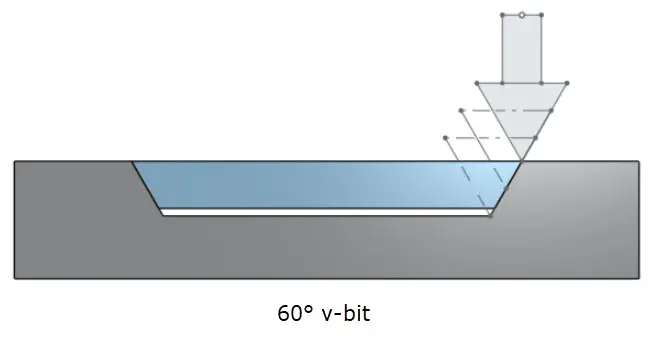
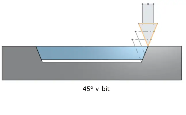
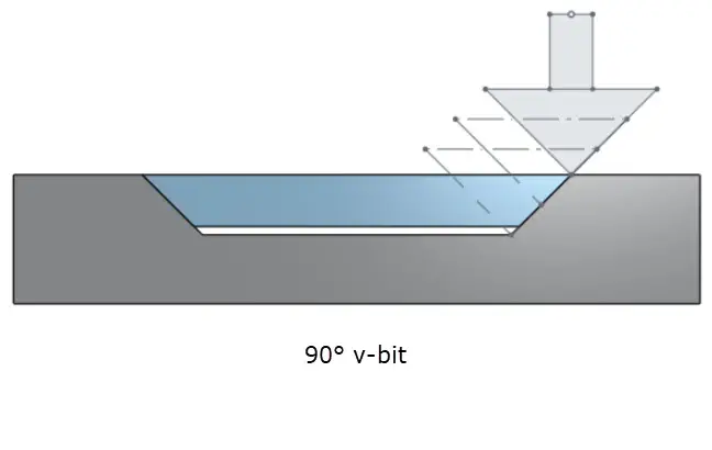
Bit Angle and Diameter
There are several v-bit angles you can choose from. Most common are 90°, 60°, and 45°. While these angles will change the geometry of the “walls” in the pocket and inley, the but will not change the depths of the toolpath. There are many reasons to use different v-bit angles but that discussion is for another article (after I figure out what they are.)
As you can see in the following images, the v-bit angle is not affecting the depths set in the CAM software.