Calculating the maximum depth with a CNC router can be tricky and not always a matter of calculations. Whether a CNC router or mill, the depth depends on the selection of tooling, chip load, the RPM, and the feed rate.
Typically, most CNC bits have a limited cutting length which will work best when cutting cavities with a depth of 2 to 3 times their diameter. Yet, the maximum depth for a CNC router is only part of the more important factor: Chip Load. Chip Load can be calculated using the two categories, shown below. With each category, the general rule of thumb may vary. An overview is provided in the chart below.
| Radial Depth of Cut (RDOC) | Impacts peripheral milling |
| Axial Depth of cut (ADOC) | Varies in slotting |
In the following sections, we’ll go deeper into discussing the general requirements and determination of cutting different types of depth with your CNC router. All of these parameters are closely tied to the chip load, travel speed, and much more, as mentioned in the introduction, so we’ll dive into that in the consecutive sections.
How to Determine the Depth
Let’s go a little deeper into each category to determine the depth. What are the main differences between the two categories? Do each types of cuts vary depending on the project?
To answer these questions, let’s first review two more definitions to understand what kind of engagement and workpiece we are trying to achieve.
Peripheral Milling
Peripheral milling is when only a part of the tool is engaging with the part. For example, when the tool is only engaging with an edge of a workpiece, this is referred to as a peripheral milling.
For easy understanding, peripheral milling can be split into 3 categories, depending on depth, 1 being the lightest and 3 being the deepest:
- Finishing,
- Light Roughing, and
- Heavy Roughing
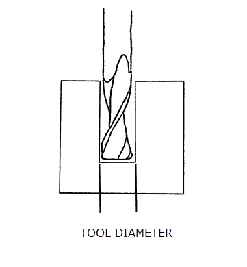
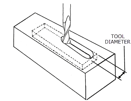
Slotting
Slotting is when the entire tool’s diameter is engaging with the part. This would be when you are manufacturing a design in the middle of a sheet of metal, wood, etc. This would normally be experienced during the first pass of a pocket operation.
Now let’s get into the two different kinds of cuts.
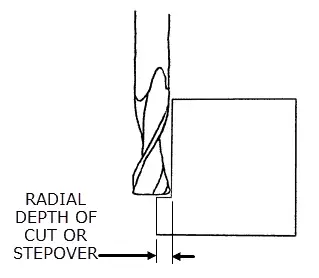
Radial Depth of Cut
Radial depth of cut, RDOC, is also known as a stepover, cut width, or XY. This is the area, or distance, a tool is stepping into the part. Only a part of the cutter is engaged with the material. Stepover is usually calculated as a percentage of the bit diameter and is incremented with each material removal pass.
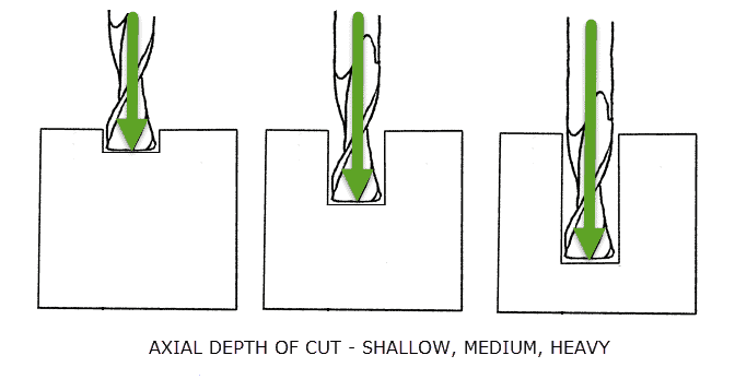
Axial Depth of Cut
Axial depth of cut, ADOC, is often referred to as the cut depth, stepdown, or plunge cut in woodworking. This is the depth that the tool will engage with in the part. Easily visualized as the depth of the tool from the side view. Like stepover, the plunge cut is incremented with each pass of material removal.
Plunging directly into a workpiece of any material is hard on the router bit and can significantly shorten its life. As an alternative to reach the desired depth, a combination of axial load and radial load can be applied. This is called ramping. Ramping will move the bit in the XY plane while slowly plunging the bit in the Z-axis forming a ramp.

Understanding General Patterns Between RDOC and ADOC for Depth
Now, let’s review how the RDOC and ADOC may vary depending on each situation. For best understanding, we’ll see the RDOC and ADOC relationship depending on the type of engagement, peripheral or slotting.
Peripheral Milling
For peripheral milling, as the RDOC increases, the ADOC will decrease. This is a general rule of thumb due to the stress load it has on the tool when engaging with the material from the periphery.
Now, remembering the 3 main categories from the peripheral milling definition, reference the relationships below.
| RDOC | Finishing | < | Light Roughing | < | Heavy Roughing |
| ADOC | Finishing | > | Light Roughing | > | Heavy Roughing |
Slotting
Slotting is generally the type of engagement that can dull your tools or worse, damage it. Generally, the depth of the slot can be matched to the lengths of cuts and the cutter diameters.
| Shallow Slots | Medium Depth Slots | Full Depth Slots |
| > 0 – 0.25 x cutter diameter | > 0.25 to 0.5x cutter diameter | > 0.5 to 1.0 x cutter diameter |
General Recommendations
For good CNC practices, limit the depth of cavities to remain in the best depth for your tool.
- Limit the depth of cavities to 4 times their length.
This ensures that there is a sufficient amount of space for a smooth entrance and further ramping into the depth.
- Typically, most CNC tools have a limited cutting length which will work best when cutting cavities with a depth of 2 to 3 times their diameter
- Example milling tool size and recommended cutting depth
| Milling tool | Recommended cutting depth |
| Æ12 milling tool | Up to 25 mm deep |
- Some argue that you are able to cut deeper, up to 4 times the diameter, but with deeper the depth, the greater the cost is wasted when it comes to material.
High Efficiency Milling (HEM)
Now, let’s briefly touch on strategies such as High efficiency milling. HEM is a method utilizing RDOC and ADOC combinations (generally light and heavy, respectively) with alternate feed rates to achieve efficient metal removal with low tool wear.
When light RDOC is paired with high ADOC, cuts are generally more uniform and the general stress distribution across the tool is uniform as well which promotes the low tool wear.
Although in traditional methods, feed rates were not fluctuated while utilizing the light RDOC and high ADOC combination, HEM promotes increasing the feed rate, such as the following.
| RDOC | 7-30% |
| ADOC | 2x the cutter diameter |
| Feed Rate | Increased feed rate |
(Source: HarveyPerformance)
Fundamental Calculations for Travel Speed
Now that we’ve reviewed the general rule of thumbs in determining the depth of a cut, let’s review some fundamental calculations. These are important values to understand to have a successful project and to prolong your tools.
With the following sections, we’ll be able to find the travel speed of your tools. We’ll use an example with these conditions to follow through and find the final travel speed:
| Material | Mild Steel |
| SFM | 100 |
| Tool Diameter | 0.750 in. |
| Number of flutes | 3 |
Spindle Speed
Spindle speed, also referenced as RPM, is the rotational speed of your tool in revolutions per minute. To generally calculate the RPM, if not provided, would be by finding the square feet per minute, SFM, of your material. Below is an example of some common (milling) materials.
- Stainless steel – 40 SFM
- Mild Steel – 100 SFM
- Brass – 300 SFM
- Aluminum – 400 SFM
To calculate, you can use a constant multiplier of 3.82. Although it’s proved by a rather long formula, 3.82 will be a safe variable to use. This is assuming you use inches.
RPM=(3.82 x SFM)/(Tool Diameter)
Side note: If you were ever curious of what your SFM may be by knowing your RPM, you can also reverse the equation to below,
SFM=RPM x 0.262 x Tool Diameter
Now let’s find an example spindle speed in RPM for mild steel with a tool diameter of 0.750 inches
RPM=(3.82 x 100)/0.750
So, the spindle speed will be 509 RPM. As for plywood with CNC routers, the slowest RPM you will experience 10,000 to 12,000.
Chip Load
Chip load, also known as the feed per tooth, is an important tool for machining. In general, you want to control your chip load, so you don’t see any over-heating. With smaller chips, you may find that it’s easier on your router and the tools, but this may cause over-heating. On the other hand, larger chips may be harder, but do pull away more heat.
With more loads, you will experience the value of chips that fall to the floor and can easily be picked up with suction rather than float and stay in the air.
Take the cutter diameter and divide by 200. In our example, our 0.750 tool indicates a 0.750 diameter.
Feed per Tooth= 0.750/200
Our chip is 0.00375 feed per tooth.
Feed Rate
Feed rate is ultimately the speed at which the surface at the center of the rotating tool engages with the part per unit of time (usually minutes). Often, feed rate is referred to as IPM, for Inches Per Minute. For the calculation, you will essentially use everything we’ve found in the previous sections.
Feed Rate = Spindle Speed (RPM)x Number of Teeth (or flutes) x Chip Load (feed per tooth) x Cutter diameter
In our example, Feed rate will be
Feed Rate=509 (RPM) x 3 flutes x 0.00375 x 0.750
Our final Feed rate will be 4.29, or roughly 4 inches per minute.
You can follow a similar example using the same equation in this video.
Additional Tips to Keep in Mind
Now let’s take a closer look at the parts and some signs of how to limit your gantry deflection, burn marks, and to determine how many safe passes to make. Let’s start with how many passes are recommended.
Safe Passes?
It’s always a good method to start with shallow passes, especially on plywood. This helps keep edges cleaner and for the pattern to be best engraved into the material with good quality.
As a general rule, that comes odd at first. Yet, it is actually recommended to continue with a shallow pass for more efficiency and speed. Often times a deeper pass takes more time and could sacrifice material and efficiency overall.
Burn Marks on Parts
If we are looking at CNC routers in specific, they are generally built for softer products such as wood, plastics, acrylic, and other soft materials including soft metals. Most times when you are working with plywood, for example, you will find burn marks. Burn marks are indications of heat buildup from a slow run.
For example, after a run, you may want to check by touching your part (always be cautious and let it cool, if necessary). That being said, this is where you will be able to utilize calculating the best feed rate.
- If it is too hot to the touch, then lower the spindle speed or increase the feed rate.
- If it is wavy – this is a sign of tool chatter and feed rate should be decreased or your spindle speed should be increased
Calculating Gantry Deflection
Gantry deflection occurs when the CNC is under load. This happens most of the time, but too much load will generally mean a short life with your beloved machinery.
Deflection can be calculated as the following.
Unsupported Length2 or Height of Beam-3
This means, when there is a gantry 2x the length, then 22= 4. Therefore, the deflection will be 4x under the same load. For a gantry that is 2x the height, then 2-3 = 1/8, therefore it will deflect 1/8x under the same load.
This means that a shorter and taller span will result in less deflection.
(Source: Scottstuff)
Bit Geometry
Knowing your bit geometry may seem logical but I wanted to mention it here. In general, you will want to use the shortest bit that will do the required job. This is for stability and to reduce the possibility of runout and chatter.
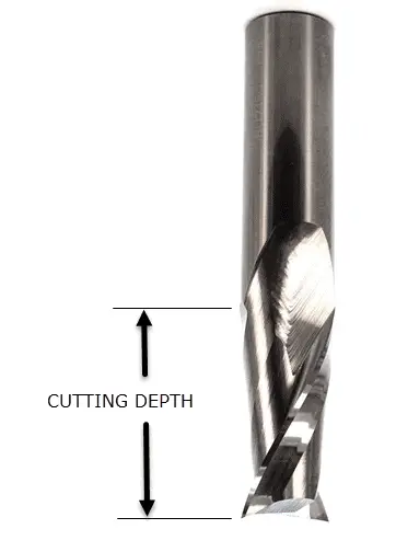
The bit has a given cutting height. This is a parameter of the bit given on its sales page or labeling somewhere. If this depth is exceeded, excessive heat will build up and burn the workpiece.
The total ADOC should never exceed the cutting depth of the router bit.
Final Thoughts
Overall, many factors will affect your final product. Proper setup and proper tools will take your projects to the next level of satisfaction. The wear and tear of your CNC router will also be reduced when the tools are set up properly. For now, make it a habit to sit down and do some calculations before moving on with your project. In time, these parameters will be a matter of knowledge and not calculations.