A CNC machine itself is just a dumb piece of equipment. It has no idea what you want to do or how it should accomplish the task. So, really, this article will be about the software that drives the machine and not really about the machine itself because that is how a CNC machine knows where to start.
It all starts with the design process. Most jobs will consist of 4 steps:
- Design Concept. Conceiving the design in your mind. You may have a customer that wants something specific or you may want to duplicate something for yourself that you saw in a magazine or at the store. Either way, you start countering up a design based on your ideas.
- CAD (Computer-Aided-Design) – Putting the design onto “paper”. This step will develop your ideas and start to turn them into a solid plan in CAD software. This is where you can work out joints, lengths, special geometry, and other aspects of the design. It is during this step also when we decide which parts need to be cut on the CNC machine.
- CAM (Computer-Aided-Manufacturing) – Now you take your design and plan out how to cut it on the router table. Not all aspects of your design will be executed on the CNC router table but since you asked how the CNC machine knows where to start, this is the route we are taking. In this step, we calculate the cutter path (including where the cutter starts), the cutting depth, and cutting speed. In some cases, the bit RPM will also be calculated at this step.
- Controller Software and hardware. The last step is to take all of the toolpaths created in CAM and convert the information into “Steps” for the CNC controller to communicate to the driving motors (Called “Stepper” motors but it got confusing using “Step” in different contexts in the same paragraph). The controller software and hardware work together to interpret the code that was generated during the CAM stage into tiny moves that represent the geometry that you originally conceived back in the Design Concept stage.
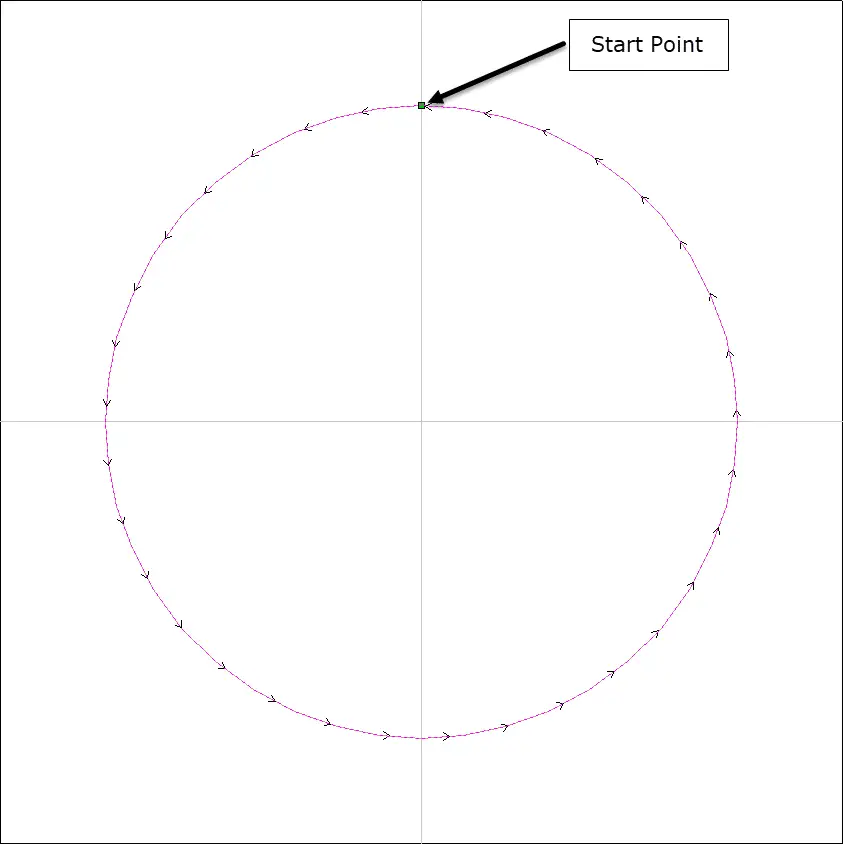
With this information, you can begin to understand that the CNC Machine knows where to start because YOU told it where to start during the toolpath creation in the CAM software. The starting point is usually at a corner by default but can be changed to start at a more convenient place in the geometry.
How Does a CNC Machine Know How Fast To Go?
This is also defined during the CAM stage and the information is conveyed to the machine through the controller software. As the toolpaths are created in the CAM software, every aspect about the material removal is defined. Among these parameters is the speed the spindle will travel. This speed is defined in several ways but generally, it is distance per time.
For example, I use inches per minute. A metric equivalent might be meters per minute or millimeters per second.
While there are charts that help with starting values for this parameter, you will find that over time, you will be able to adjust your machine to the proper speed just by listening to the sound it makes and examining the size of the chips being produced.
The speed of the spindle works hand in hand with the RPM the bit is being driven. It is always recommended that you be able to control the RPM of your spindle. The larger the bit diameter is, the slower the RPM should be adjusted.
How Does a CNC Machine Know Where to go Next?
Again, as you create the toolpath in the CAM software, you are defining very small point to point moves that the CNC machine will follow to represent your design. In many cases, even curves and circles are broken down into very small lines. While some post-processors (the software that converts your CAM toolpath into a text file of G-Code that the controller software reads) can interpret curves and circles mathematically, most post-processors used by the hobbyist woodworker probably breaks circles and curves into tiny lines.
Post-processors and G-Code are a little beyond the scope of this article but for the sake of understanding better, here is an example of G-code created by my GRBL post-processor and by my MACH3 generic post-processor.
| Circle Calculated | Circle Interpreted |
|---|---|
| ( MACH3 ) ( File created: Wednesday July 08 2020 – 11:00 PM) ( for Mach2/3 from Vectric ) ( Material Size) ( X= 1.000, Y= 1.000, Z= 0.125) () (Toolpaths used in this file:) (Profile 1) (Tools used in this file: ) (1 = End Mill {1/4″}) N100G00G20G17G90G40G49G80 N110G70G91.1 N120T1M06 N130 (End Mill {1/4″}) N140G00G43Z0.9250H1 N150S18000M03 N160(Toolpath:- Profile 1) N170() N180G94 N190X0.0000Y0.0000F80.0 N200G00X0.0000Y0.3750Z0.3250 N210G1Z0.0050F50.0 N220G3X-0.3750Y0.0000I0.0000J-0.3750F80.0 N230G3X0.0000Y-0.3750I0.3750J0.0000 N240G3X0.3750Y0.0000I0.0000J0.3750 N250G3X0.0000Y0.3750I-0.3750J0.0000 N260G00Z0.3250 N270G00Z0.9250 N280G00X0.0000Y0.0000 N290M09 N300M30 % | T1 G17 G20 G90 G0Z0.9250 G0X0.0000Y0.0000S18000M3 G0X0.0000Y0.3750Z0.3250 G1Z0.0050F50.0 G1X-0.0099Y0.3749F80.0 G1X-0.0198Y0.3745 G1X-0.0299Y0.3738 G1X-0.0400Y0.3729 G1X-0.0502Y0.3716 G1X-0.0605Y0.3701 G1X-0.0708Y0.3683 G1X-0.0812Y0.3661 G1X-0.0915Y0.3637 G1X-0.1019Y0.3609 G1X-0.1123Y0.3578 G1X-0.1226Y0.3544 G1X-0.1329Y0.3507 G1X-0.1432Y0.3466 G1X-0.1534Y0.3422 G1X-0.1635Y0.3375 G1X-0.1735Y0.3325 G1X-0.1834Y0.3271 G1X-0.1932Y0.3214 G1X-0.2028Y0.3154 G1X-0.2123Y0.3091 G1X-0.2216Y0.3025 G1X-0.2308Y0.2956 G1X-0.2397Y0.2884 G1X-0.2484Y0.2809 G1X-0.2569Y0.2732 . . 228 Lines total . G1X0.0099Y0.3749 G1X0.0000Y0.3750 G0Z0.3250 G0Z0.9250 G0X0.0000Y0.0000 M02 |
There is no doubt that a woodworker who wants to include a CNC machine in their arsenal of tools will have to learn several new technologies. I see this growth no different than learning how to sharpen your blades or how to remove rust from cast iron surfaces. A CNC can bring much value to any shop but the most value will be seen by the shop that repeats the same – or similar – product over and over. Even name plaques can be programmed with a template that allows the wording to change while everything else remains the same.
Don’t let the mysteries behind the CNC curtain keep you from increasing productivity in your shop.